Started in 1956, the British journal Nuclear Engineering frequently published large, fold-out ‘wall charts’ of relevant reactors and atomic power stations. Titled The World’s Reactors, the series runs (as best this author can tell) from April 1956 to about 2004, with 105 charts in total for the corresponding 97 volumes. While the journal remains active at the time of writing (now owned by Springer Publishing of New York), multiple reorganizations and acquisitions caused the publishers to lose the original illustrations. Wanting to preserve these ubiquitous charts, Ronald A. Knief of Sandia National Laboratories lead an effort to collect and scan extant copies, all digitalizations of which are now available at the University of New Mexico’s Digital Collections.
While there are 105 in total, the ‘golden years’ of theses charts dates from 1957 to 1974, when the draftsmen Tony Lofthouse and R. John Way illustrated the majority of the 52 drawings corresponding to that period (when authorship could be attributed). I have been unable to find any additional information on these illustrators, and would be much obliged if anyone with more information could share.
These drawings are things to behold.

Way, R. John, illustrator. “The World’s Reactors No. 46: St. Laurent des Eaux.” From Nuclear Engineering International, August 1969.
Employing the technique of cut-away two- and three-point perspective, they unveil in lavish detail the complex systems and sublime spaces of atomic power generation. They use airbrushed retro colors. They provide little scientists in lab coats to show scale. They – at different moments – prioritize the knotted ductwork which sustains the reactors and the pure industrial volumes which contain them. The imagination and skill of the illustrators cannot be overstated as they had to both construct a complex perspectival composition – often using just technical drawings provided by the reactor designers – and then deconstruct that same image in order to reveal the inner workings.
In any given chart, the eye is presented with a veritable I-spy of rooms, pipes, gantries, and typically several feet of pre-stressed concrete. If the original charts are overwhelming, the thesis of the following images is that they can be further appreciated by a naïve act of cropping. We can focus on a single Piranesian vignette or medusa-like system. We can allow the ingenious construction of the section plane cuts to read through the flatness of the new whitespace. Pre-Three Mile Island, pre-Chernobyl, these drawings are full of the atomic energy optimism which – to lay my cards on the table – is likely a necessary part of de-carbonization. This is the first set in the series which I hope to continue.
Please enjoy them and see if you can tell the fuel handling machines from primary coolant loops. This is the first set in the series which I hope to continue.
—Dylan
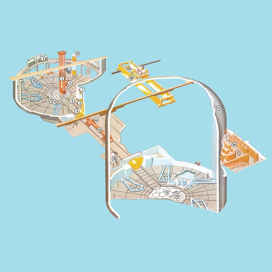
Fulton Generating Station Units 1 and 2. Designed: 1974ca. Unbuilt. 2x HTGR Type Reactors: Graphite Moderator, Helium Coolant, Uranium-Thorium Fuel. Nominal Power: 600 MWt ea. / Draftsman: R. John Way / 3. Fuel handling machine 4. Plug actuator 5. Equipment hatch 6. Personnel hatch 7. Fuel handling machine trolley hoist 8. Fuel handling machine trolley rails 9. Containment clean-up filter units 10. Elevator machinery room 11. Containment ventilation system duct 12. Containment clean-up system fancs 13. Core auxiliary heat exchanger piping 14. Reactor containment 2 15. Refueling floor 16. Refueling floor hold-down plates 38. Reactor service building crane 44. Fuel handling transfer dolly 45. Auxiliary service cask 56. Liquid nitrogen storage tanks 64. Control room for unit 2
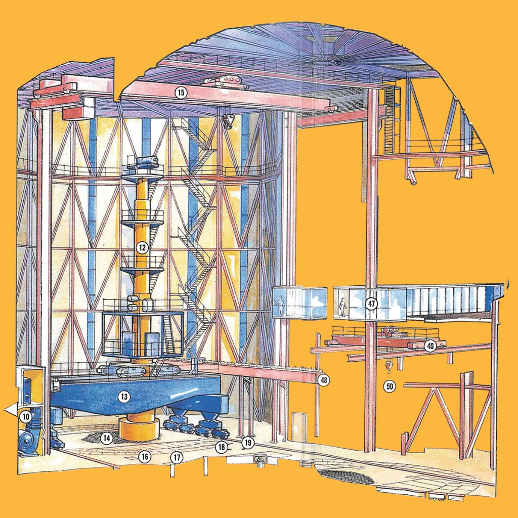
Dungeness B. Construction 1965-83. Operation 1983-2021. AGR Type Reactor: Graphite Moderator, Carbon Dioxide Coolant, Natural Uranium Metal Fuel. Nominal Power: 1,320 MWt. / Draftsman: R. John Way / 10. Charge hall ventilation plant 12. Fueling machine 13. Fueling machine gantry 14. Charge face for Reactor I 15. Fueling machine maintenance crane 16. Control rod service hole 17. New fuel service hole 18. Fuel stringer storage hole 19. Irradiated fuel disposal hole 47. Charge hall viewing gallery 48. Cable drag chain for fueling machine 49. Maintenance bay crane 50. Fueling machine maintenance area
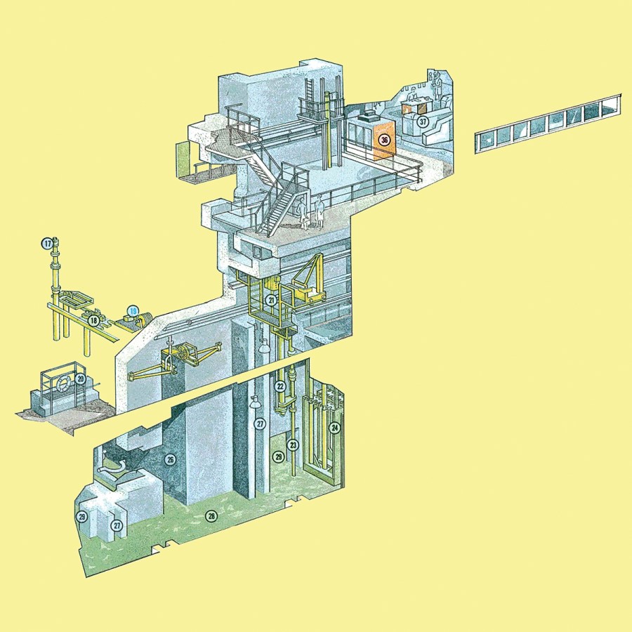
Winfrith Prototype Reactor. Construction 1963-67. Operation 1967-1990. SGHWR Type Reactor: Heavy Water Moderator. Water Coolant, Lightly-Enriched Uranium Fuel. Nominal Power: 100 MWt. / Draftsman: R. John Way / 17. Charge-discharge facility 18. Tunnel transfer trolley 19. Trolley fuel lifting gear 20. Bridge mounting platform 21. Pond bridge crane 22. Periscope 23. Fuel stringer 24. Fuel stringer racks 26. Fuel element transfer tunnel 27. Damgate channels 28. Fuel element pond 29. Suppression pond relief openings 36. Acoustic booth 37. Control room
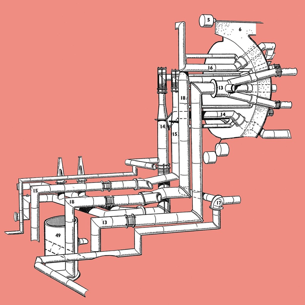
Marcoule Units G2 & G3. Construction 1955-59 / 1956-60. Operation 1959-80 / 1960-84. 2x UNGG Type Reactors: Graphite Moderator, Carbon Dioxide Coolant, Natural Uranium Metal Fuel. Nominal Power: 40 MWt ea. / Draftsman: Tony Lofthouse. / 5. Concrete Pre-Stress Cables 6. Vessel and Biological Shield 13. Primary Central Inlet 14. Primary Central Outlet 15. Primary Peripheral Inlet 16. Primary Peripheral Outlet 18. Secondary Outlet 49. Heat Exchangers
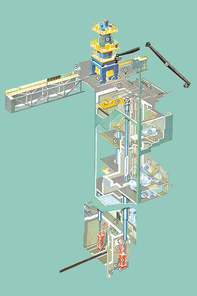
St. Laurent des Eaux Units A1 and A2. Construction: 1963-1969. Operation: 1969-1990/91. 2x UNGG Type Reactors: Graphite Moderator, Carbon Dioxide Coolant, Natural Uranium Metal Fuel. Nominal Power: 390/450 MWt ea. / Draftsman: R. John Way / 19. Spent fuel discharge position – south 20. Access to service bay 21. Spent fuel discharge position – north 22. Access to test bay 23. Service station bridge crane 24. Service station 25. Test station 27. Supply conveyor for rotating fuel manipulator 28. Room for loading lock-chamber with new fuel 29. South lock chamber 30. Control station for lock-chamber 31. Rotating fuel manipulator 32. North lock chamber 33. Shock absorber 34. Chutes 37. Tanks for shut-down heat exchangers 38. Raw water containers 39. North transfer tanks 40. Concrete vessel coolant tanks 43. Charge machine 48. Charge machine control – compass arms 50. Handling shaft 51. Charge machine transporter 52. Transporter control 74. Skirt
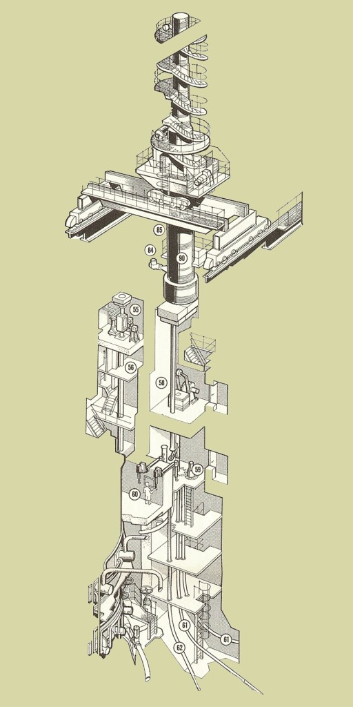
Hinkley Point B. Construction: 1967-76. Operation 1976-2022. 2x AGR Type Reactors: Graphite Moderator, Carbon Dioxide Coolant, Lightly Enriched Uranium Fuel. Nominal Power: 660 MWt ea. / Draftsman: R. John Way / 55. New fuel cell 56. Lower new fuel cell 58. Irradiated fuel dismantling cell 59. Bottling machine 60. Manipulators 61. Fuel disposal tubes 62. Tie rod disposal tubes 84. Test facility cover 85. Charge machine maintenance well cover 90. Charge machine
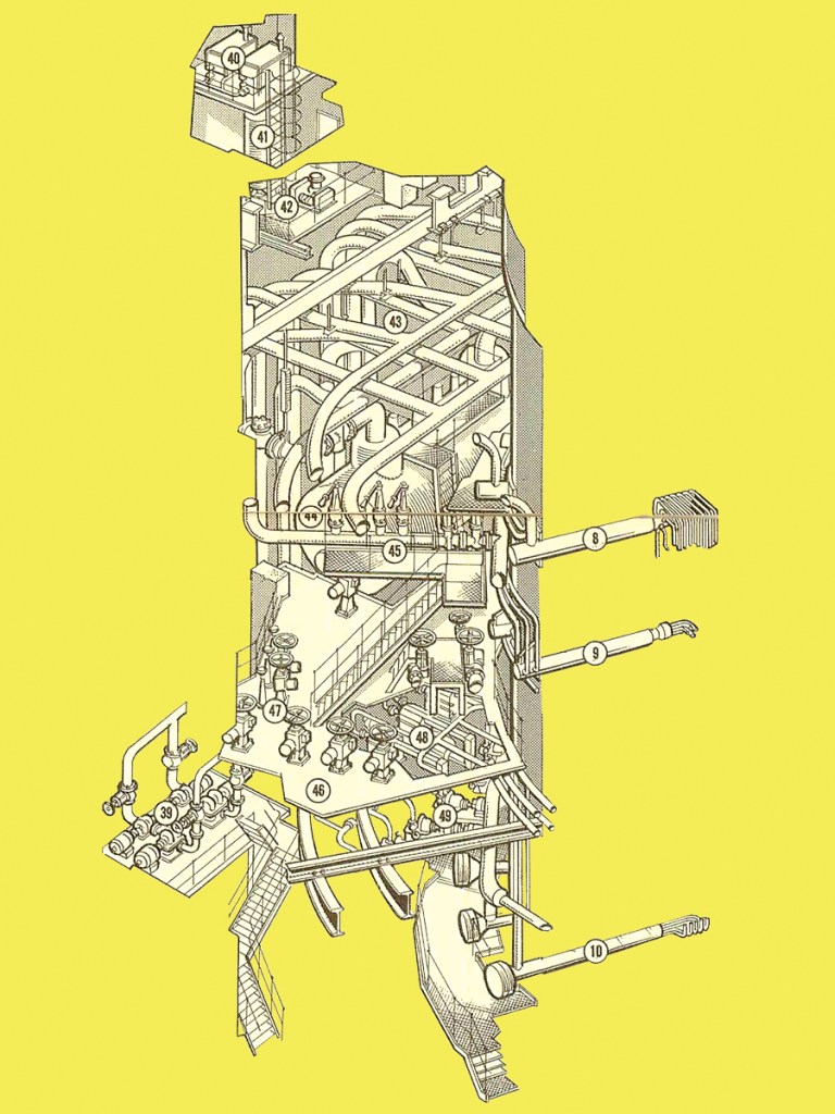
Hinkley Point B, cont’d. / Draftsman: R. John Way / 8. Reheat penetration 9. Main steam penetration 10. Feed penetration 39. De-gasser extraction pumps 40. De-gasser pressure setting tanks 41. De-gasser 42. De-gasser vacuum pumps 43. Steam pipe well 45. L.T. relief valves and access platform 46. 66 ft. level platform 47. Steam valves (pedestal control) 48. Pressure vessel treated water coolers 49. Auxiliaries system treated water pumps
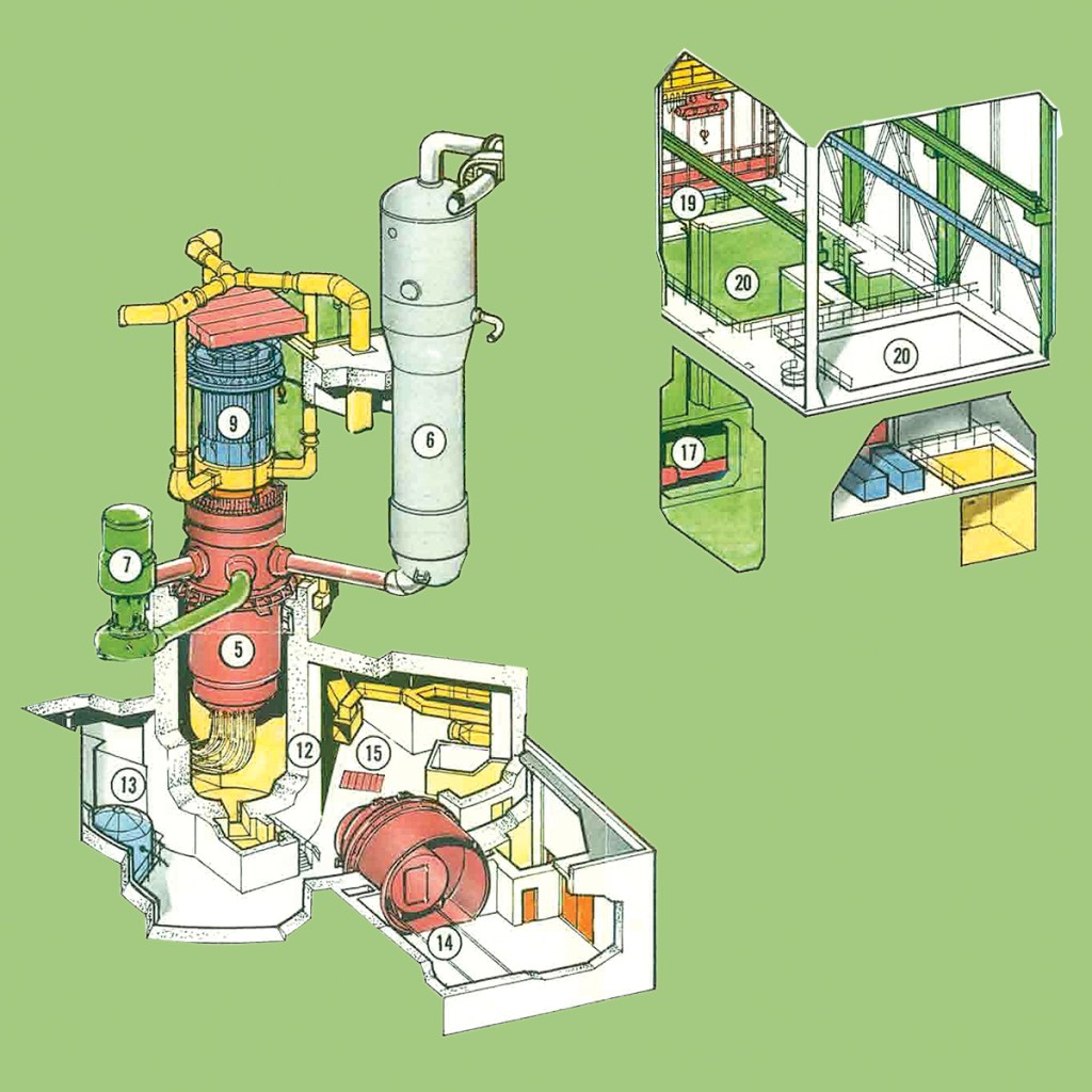
Fessenheim Units 1 and 2. Construction: 1970/71-76. Operation: 1976-2020. 2x PWR CP0 Type Reactors: Pressurized Water Moderator, Pressurized Water Coolant, Enriched Uranium Fuel. Nominal Power: 900 MWt ea. / Draftsman: Tony Lofthouse / 5. Pressure vessel 6. Steam generators 7. Reactor coolant pumps 9. Control rod drive mechanisms 12. Biological shield 13. Safety injection accumulators 14. Equipment air lock 15. Containment ventilation 17. Fuel transfer tube 19. Fuel transfer canal 20. Spent fuel pit skimmer pump
Nuclear Reactor Fragments – 01 / 2024
